By Remi Bennett · Humanoid robot data · · 9 min read
How to Check Camera and Action Timing in Robot Training Data
A camera frame and a robot command can have matching timestamps without describing the same physical moment. The camera timestamp might mean when an image reached the computer. The command timestamp might mean when a target was sent, not when the fingers moved. Joining those records perfectly can still produce the wrong training example.
To check data synchronisation, start by establishing what each timestamp measures and whether the clocks are comparable. Then test the timing against an observable event, keep observation delay separate from execution delay, and verify that the exported training sample preserves the intended relationship. Equal row counts and a smooth replay are not enough.
The Universal Manipulation Interface, or UMI, makes this unusually concrete. Its paper treats latency matching as part of getting a policy trained on handheld demonstrations to work on a robot. The problem is not simply saving the demonstration correctly. It is preserving its timing meaning when different cameras, controllers and actuators enter the loop.
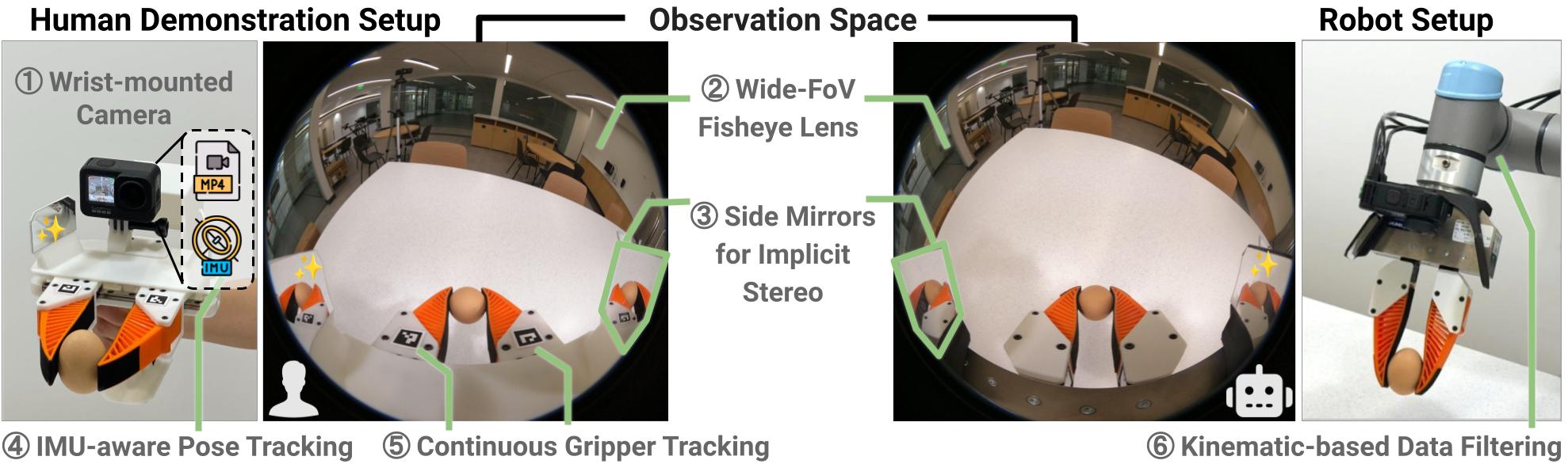
UMI connects handheld demonstration collection to robot execution. Similar camera views help, but do not establish equal sensing or actuation delays. Source: UMI project authors. The figure illustrates the hardware, not a timing test performed for this article.
A timestamp needs a physical definition
The first thing I would ask a supplier is where the timestamp is created. “Nanoseconds” answers the unit. “UTC” identifies a time convention. Neither tells us which event was timed.
The ROS Image message definition says its header timestamp should be the image acquisition time. That is a useful contract, but the word “should” matters: a dataset still needs evidence that its particular driver follows it. For a camera, also establish what acquisition means in that device's exposure and readout process.
A container can hold different time meanings alongside the image. In the MCAP specification, log_time is when a message was recorded; publish_time is when it was published. If publication time is unavailable, the specification requires it to be set to log time. Equal values can therefore mean that a measurement is missing, not that the camera-to-recorder path had zero delay. An acquisition timestamp may instead live inside the encoded message.
For a demonstration, preserve these distinctions wherever the system exposes them:
- Observation time: when the sensor sampled the scene or measured the robot state.
- Receipt time: when that observation reached the process using or recording it.
- Command time: when a target was issued, plus its desired execution time if the controller supports scheduled commands.
- Measured response time: when feedback reports the resulting state, with the feedback stream's own delay accounted for.
These are meanings to document, not a demand that every device magically expose every field. An estimated capture time can be useful. An estimate labelled as a direct hardware measurement is misleading.
That distinction surfaced when I inspected UMI's camera implementation at commit d095ba9. It retains camera receipt and capture fields, but the timestamp used for alignment is computed as receipt time minus a configured receive latency. The field name alone would not have told me that. This is why inspecting the exporter or driver can be more useful than reading the dataset's headline frame rate.
Matching messages does not calibrate clocks
Clock synchronisation and stream alignment solve different problems. Clock synchronisation makes time values comparable. Alignment chooses which samples to pair once that relationship is known.
If the camera clock and robot clock have different origins, subtracting their raw values does not measure transport delay. If their relationship changes over a recording, a single offset fitted at the beginning may not describe the end. Keep the clock source, conversion rule and any reset or discontinuity visible in the delivered data.
ROS's ApproximateTimeSynchronizer implementation groups messages using their header timestamps within a tolerance. It also warns against substituting arrival time for missing timestamps because delays are unpredictable. Increasing the tolerance can produce more matched pairs; it does not show that those pairs correspond to the same physical event.
The same applies to resampling. Holding the last state, choosing the nearest sample and interpolating between samples are different operations. A training pipeline should state which it uses, the tolerated gap and what happens when no valid sample exists. Interpolation across an ordinary interval is not permission to interpolate across a camera restart or a missing section of an episode.
For inputs to an online policy, there is another constraint: the information must actually have been available when the decision was made. Offline interpolation may use a later measurement to reconstruct an earlier state. That can be appropriate for analysis, but feeding such a reconstruction into training requires checking that deployment can supply an equivalent input. Otherwise, the training process quietly gives the policy information it will not have on the robot.
UMI aligns observations without pretending they are fresh
UMI's observation-latency procedure aligns streams to the highest-latency observation, usually the camera. Robot pose and gripper state are interpolated onto the image-observation timeline. The resulting bundle is internally aligned; it is not necessarily a picture of the present.
That difference matters at a moving contact. Consider an illustrative calculation, not a measurement from UMI: motion at 0.5 metres per second covers 20 millimetres during a 40-millisecond offset. Whether that is tolerable depends on the task, geometry and phase of motion. “Within one frame” is not a useful acceptance rule until the physical consequence of that frame is understood.
The camera-calibration appendix describes filming a rolling timestamp QR code. Its estimate subtracts the timestamp shown on the display and the known display-refresh latency from the frame's receipt time. The test measures a path through the camera and capture system, not just the advertised sensor rate.
The display correction is important. I would not treat any filmed-clock test as ground truth without accounting for when the displayed content became physically visible. UMI's published calibration script includes a software QR-display correction, but inspecting that code does not establish an independent measurement of monitor scanout. Record the measurement method and its uncertainty along with the resulting offset.
The arm and gripper must agree on execution time
A well-aligned observation does not ensure a well-timed action. Control latency includes the path after a decision as well as the path before it, and the arm and gripper can have different delays.
UMI's gripper-calibration procedure compares commanded and measured gripper-width sequences to estimate end-to-end delay. It then subtracts observation latency to estimate action latency. Without that separation, a delay in receiving the measurement can be mistaken for a delay in moving the gripper.
The paper's action-latency matching sends commands ahead of their desired execution time, accounting for the different hardware paths. Its intended policy is to discard predicted actions that are already too late. The inspected evaluation code also has a fallback for an entirely late prediction sequence, so the paper should not be read as a guarantee that every implementation simply rejects all deadline misses.
There is task evidence for taking this seriously. In the authors' tossing ablation, the same trained policy achieved 105 successful object tosses out of 120 with latency matching, compared with 69 out of 120 when observation and action matching latencies were set to zero. The authors identify mistimed gripper release relative to arm motion as a failure mode.
Those are the researchers' results, not tests performed here. The experiment changes the timing treatment jointly; it does not isolate camera offset, establish a universal millisecond tolerance or prove that every slower task needs the same machinery. It does show why “the commands were sent together” is a weak substitute for “the intended physical actions happened together”.
Test one episode through the complete data path
For a purchase or collection acceptance exercise, I would use the following procedure. This is a proposed engineering workflow based on the distinctions above, not a published UMI benchmark.
- Write the timing contract before matching samples. List each stream's timestamp meaning, clock, sampling rate, measured delay and uncertainty. Separate direct measurements from estimates. State whether the action label is an operator request, a controller target or reconstructed motion; these are different action spaces.
- Choose an observable reference event. Use a documented timing target for the camera and an appropriately instrumented event for other streams. A casually filmed display or a tap is not automatically a shared-clock reference. For motion-based checks, use qualified operators and the hardware's approved operating limits, not arbitrary calibration-script defaults.
- Measure residual alignment under collection conditions. After applying the proposed correction, inspect several events across the recording, including its beginning and end. Repeat with the normal capture, compression and logging load. Report the residual distribution, gaps and rejected samples, not just the average offset from one clean segment.
- Inspect the sample the learner actually receives. Trace a raw image and its neighbouring state/action records through conversion into the final loader output. Confirm the action's intended time relative to the observation, the interpolation or hold rule, and the treatment of episode boundaries. Check that future feedback has not silently become an input unavailable at deployment.
- Keep the evidence with the release. Preserve original timestamps, calibration configuration, conversion version and validity masks or rejection reasons. If the dataset is resampled, retain enough provenance to distinguish real sensor samples from derived values. Define the allowable timing error from the intended task rather than adopting another project's constant.
This complements the format checks in MCAP vs LeRobot: the file format tells us how records are stored, while this exercise establishes what their temporal relationship means.
A useful final question for the supplier is simple: pick one frame just before contact, show which action it teaches, and explain why that action belongs there. If answering requires guessing when the camera saw the scene or when the fingers responded, collecting more episodes is not yet the right next step.